Choosing a notation
Process maps use symbols to designate different things within the process. In part 1 we had a simple "making tea" process map with elements such as circles, rectangles and diamonds. There are several different mapping notations, all of which are similar (after all they are doing the same thing), but it's best to choose one and stick to it. I am using a common and international notation called BPMN (Business Process Modelling Notation) but there are others such as UML which you might want to investigate before choosing one [1].BPMN can appear quite baffling in its array of symbols, but actually for the majority of models that you build you'll need only a small subset. The most common ones are listed below:
 |
Start of process or sub-process (there can only be one of these) |
 |
Exclusive gateway: only one of the emerging options is permissible (A or B or C) |
 |
Parallel gateway: all emerging paths must occur (A and B and C) |
 |
Inclusive gateway: at least one of the emerging options must happen, but two, more or all of them can happen (A or B or C or A+B or A+C or B+C or A+B+C) |
 |
Manual task: this task is performed without any system being used |
 |
User task: this task is performed by a person using a computer system |
 |
Service task: this is something a computer system does automatically with no human intervention |
 |
Sub-process: this container marks where a sub process occurs within a main process. It can be expanded to give the detailed flow within it |
 |
Conditional event: in a task this will only happen if a condition is met, otherwise the "default" flow will take place |
 |
Link event: these are always paired with the same label (e.g. Link 1). They are used to denote where one part of a process joins with another, usually when you have to split the process into two or more diagrams because of its size, or if the two links are widely dispersed (e.g. something happens near the beginning and its link happens near the end). |
 |
End event: this terminates the process or a particular branch of the process (there can be more than one in a process) |
 |
Message flow: this is used to connect tasks between two or more processes (usually the process we are mapping and another, often external one, where we only want to show there is a flow in and out, and not map the internals in any detail). |
 |
Sequence flow: this shows the sequence of how tasks flow from one to another within the process |
 |
Data object: this is simply an object that is used within the process - it can be created, edited, deleted or simply referenced but does not itself influence process flow |
 |
Association: this is the line that links a data object to a task. If there is an arrow this denotes the direction of flow - from object to task means the task simply refers to the object; from task to object means the task creates, edits or deletes the object |
These symbols are housed within a rectangular box called a pool. Within the pool there must be at least one swim lane, but there can be two or more. Each swim lane represents a role within the process, so any symbols in that swim lane represent things that role undertakes. You can have the swim lanes vertically, reading from top to bottom in the pool (and left to right across the lanes, usually); but more commonly they are horizontal, reading from left to right across the pool (and top to bottom across the lanes). The making tea process in part 1 had two swim lanes.
Choosing a drawing tool
Having selected a notation, you then need a drawing tool. Conceivably you could use Microsoft PowerPoint (or even Word), but I would advise against this as they do not have templates with the symbol elements ready-made. Many people use Visio, and it is definitely a powerful graphical drawing tool. Recent versions even have BPMN stencils as part of the package. However it is quite expensive and there are often free (or cheaper) options. For a general purpose drawing tool I recommend yED which has a Java based client or a Web browser version - both completely free. It comes with a set of stencils for different types of diagrams including BPMN (the tea process was drawn using yED). However if you intend to stick to BPMN I recommend BizAgi Process Modeler, a free application that is very powerful and dedicated to BPMN diagrams (all the models shown below were drawn in BizAgi). BizAgi also provide a series of online training videos to help you learn how to use BizAgi and the BPMN notation. (in part 3 there will be an introduction to BPMN).Drawing your process map
Converting a "brown paper" into a BPMN (or other notation) model is not usually simply copying each of the post-its onto the diagram.- Even though you may have carefully looked for all the branches during the workshop (part 1) you will often find new ones as you draw up the map, so be prepared for this.
- You'll also find that you may want to rearrange the order of swim lanes to prevent multiple cross overs.
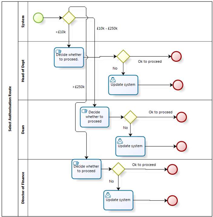
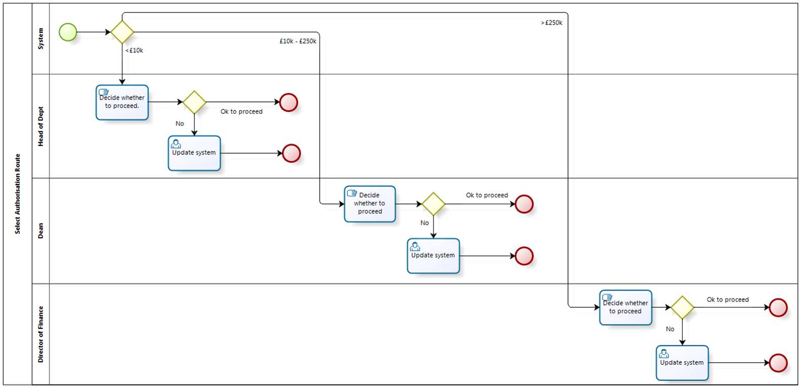
- Thirdly you'll find that spacing things out is sometimes quite difficult, and if you end up with a tangle of crossing over lines you may need to rethink how things are spaced out. The two examples below give a before and after to demonstrate what I mean (they show a process where there are three levels of authorisation for expenditure according to amount - click to expand).
- Sometimes you'll find it's almost impossible to untangle things - in this case it may be possible to put things into a sub-process. On the main diagram there is just one box, but this can be drilled into to see the details within. The authorisation process shown above is an example of this: it's a sub-process within a bigger model.
- You need to think carefully about labels on your diagram:
- Tasks should be described in verb-noun format with as few words as possible, i.e. "Brew tea" rather than "Tea brewed" or "Wait until the tea has brewed".
- Decision diamonds should be labelled with a question, e.g. Takes sugar? and then the lines emerging from it are labelled with the options (Yes, No; One spoon, Two spoons; etc.).
- Link events should be labelled in pairs with the same wording so that the linked pairs can be identified, e.g. Link 1.
- Conditional events are often joined on to a task box, in which case they aren't directly labelled, but the emerging line is labelled to indicate what the condition means - for example you may have an activity to process a form, but if it isn't received within a certain time you send out a reminder. So the task will be labelled "Process form" and the condition event's arrow will be labelled "Send reminder if form not received in 2 days", as shown in the diagram here.
- Start and end events aren't usually labelled.
- It is OK to use annotations on a diagram to help clarify things (BPMN has an annotation element) - but don't make the diagram too cluttered.
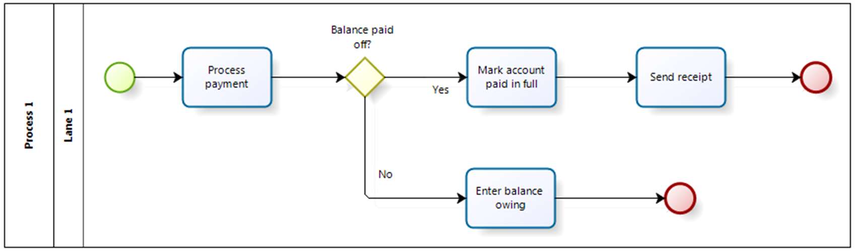
- As you complete your map check that there are no orphaned tasks (i.e. the flow goes into a task and there is no ongoing flow). It may be that you simply need an end point, but you also need to watch that, if you do include an end point, you aren't cutting off the process short. The diagram below gives a simple example (click to expand). The top flow is fine: if the account is paid in full the account is updated and a receipt is issued. The lower branch, however, updates the account if it hasn't been paid in full, but then just stops. Ideally you need to send a reminder, so if the task simply links into send receipt this will do fine (as the receipt will show the balance owing). Over time you'll gain experience of this and will be able to identify these "dead ends" more easily.
If you want more detail on using BPMN, go to part 3; otherwise you can skip to part 4 if you just want to go straight to creating the to-be process.
Reference:
[1] Paul, D., Yeates, D., and Cadle J. (eds) Business Analysis (2nd Ed) p. 136
No comments:
Post a Comment